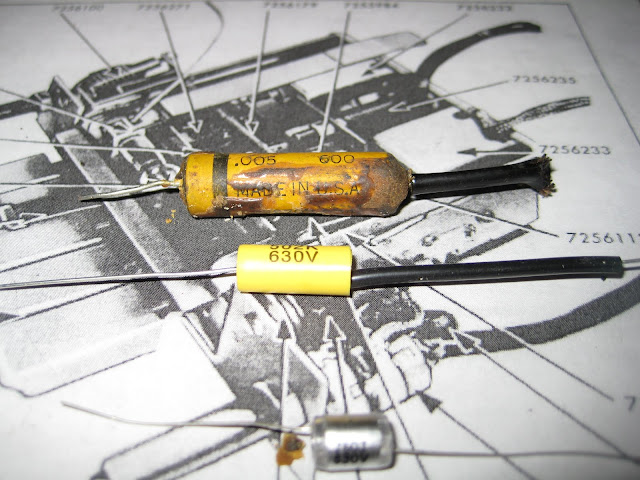
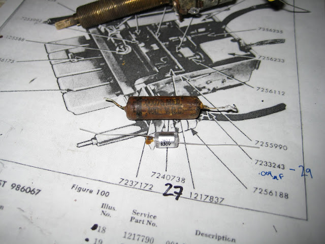
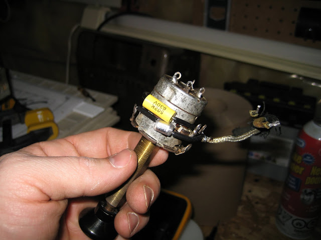
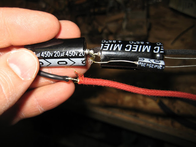
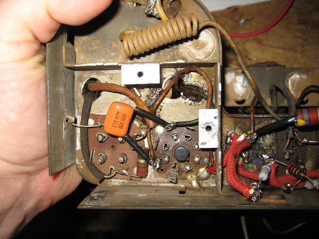
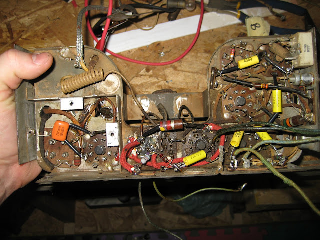
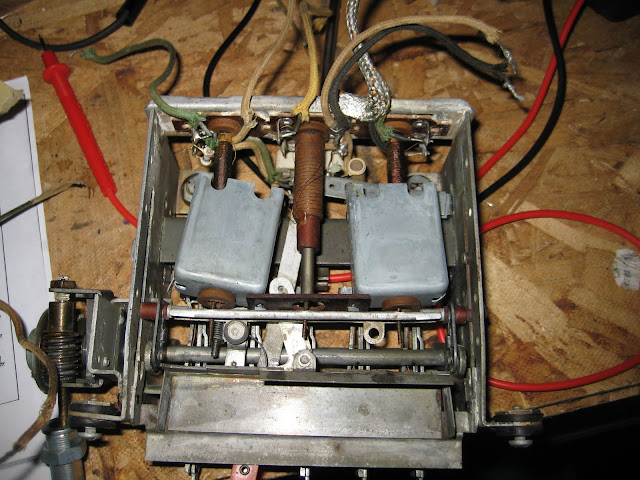
The following are before and after shots of the tone control caps on located on the volume / power / tone switch.
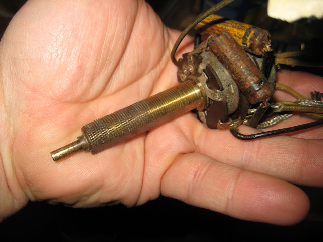
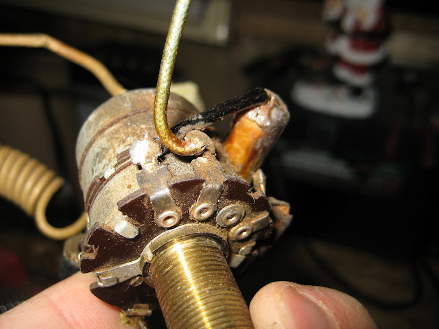
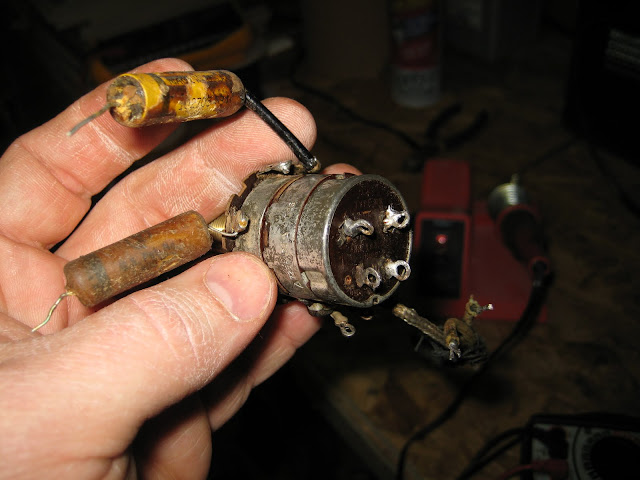
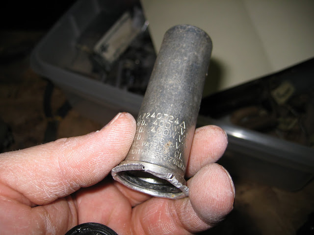
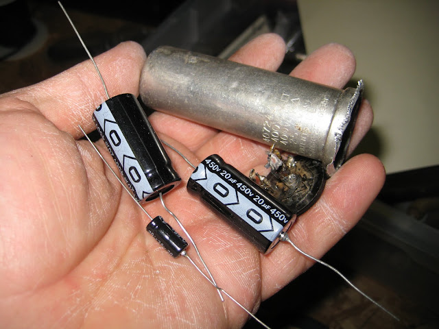
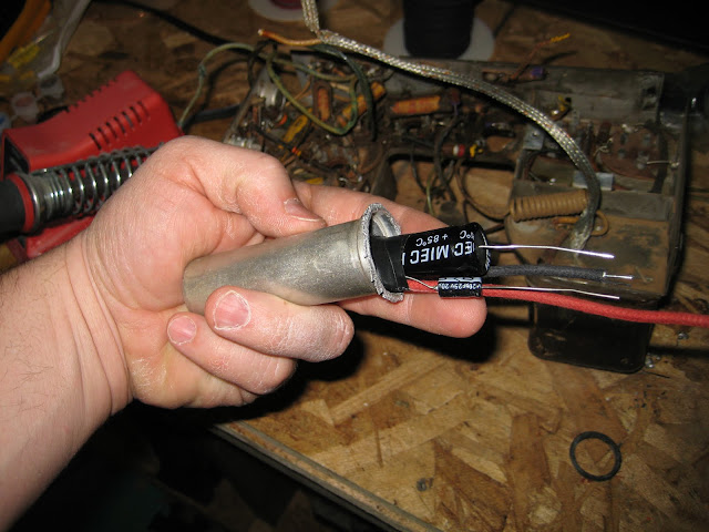
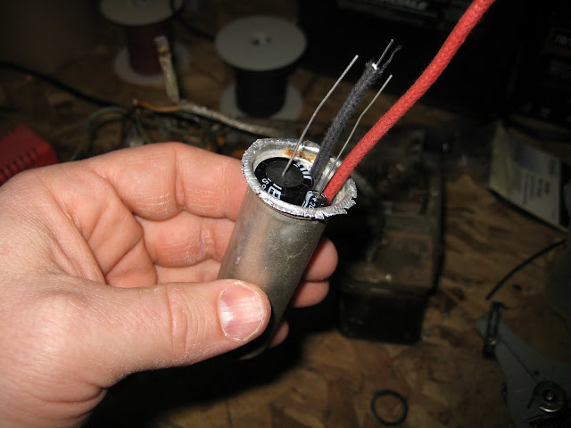
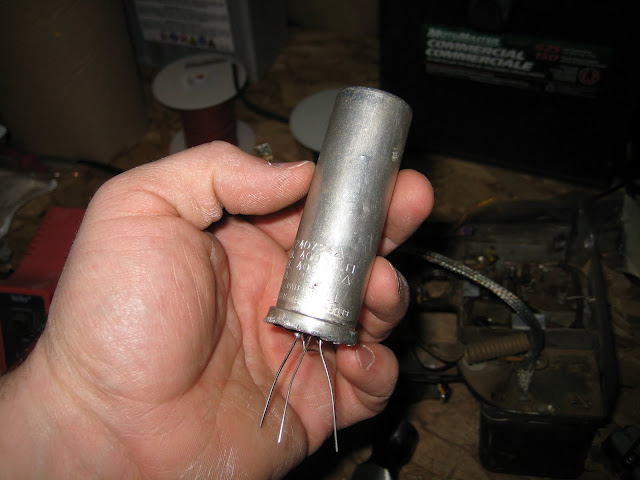
There’s a three cap can on the radio, which simple equates to a big capacitor in a can that was capable of storing three different values of capacitance. These two need to be replaced. While gutting one of these is not necessary (you can simply cut it out of the circuit and put the new caps under the chassis) , I choose to do so, and re-stuffed the can with new electrolytic capacitors.
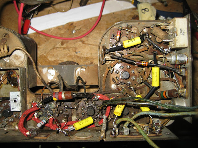
The chassis starts to light up with color as all the caps are replaced! This is the “fun” part, as the radio starts to go back together.
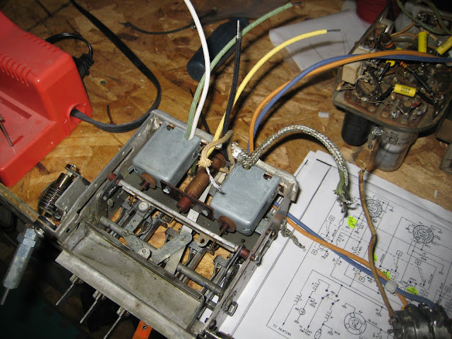
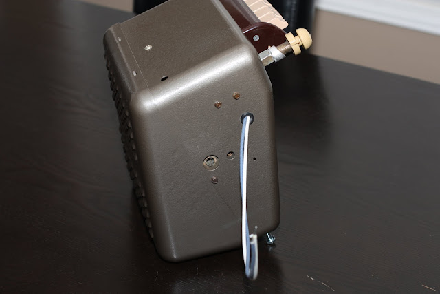
Next the tuning assemble gets all new wires, as the old were breaking and worn, and then gets reunited back with the tube chassis. I took advantage of the wire replacement to add one piece of new functionality. I put a break in the wire that feeds the AM signal to the amplifier, and inserted a 3.5mm jack to supply an external source, such as an MP3 player or iPhone.

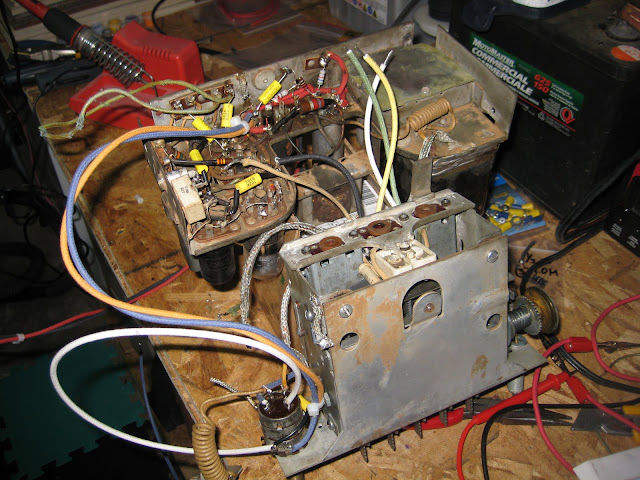
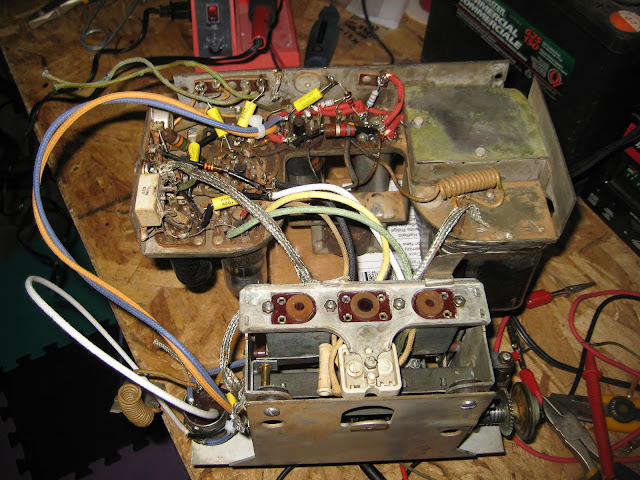

Finally – at a point where I can apply some power!
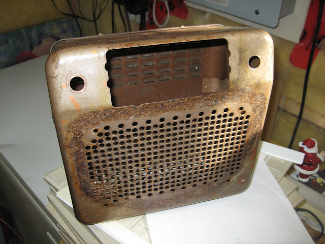
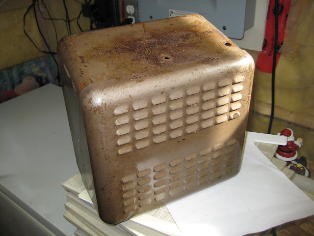
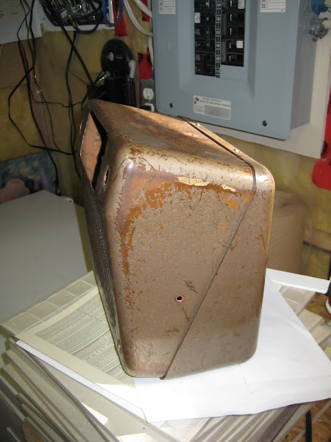
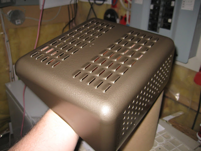
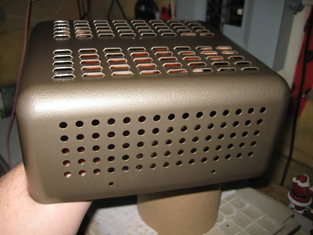
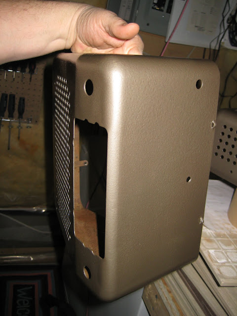
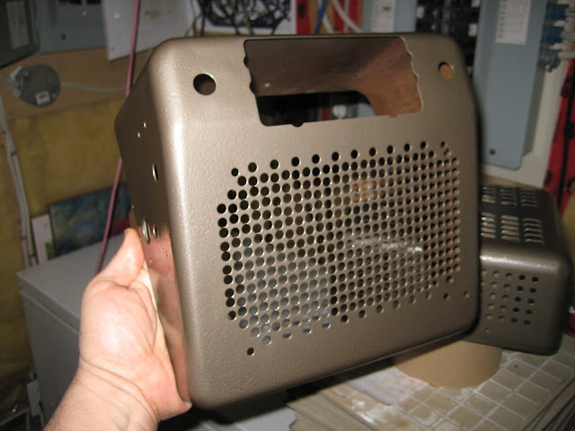
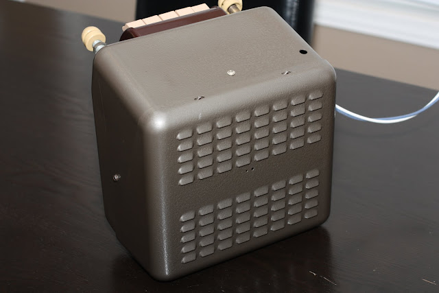
With all the electronics updated, attention turned to the copper case the radio is housed in. The top had minor pitting with a fair amount of surface rust. This is because the radio sits below the dash in front of the air vent, surly water found its way to the radio.

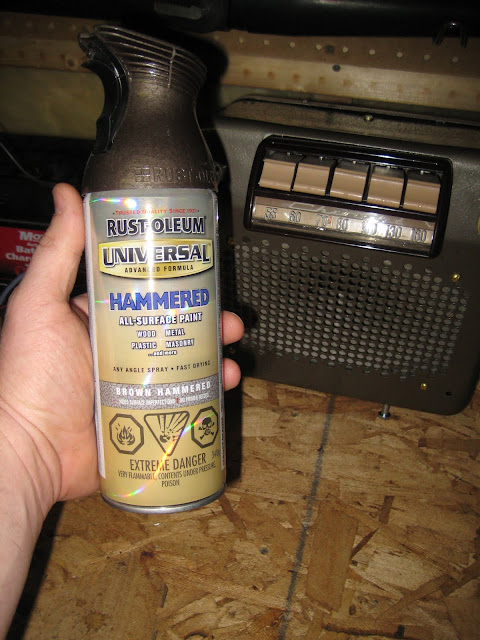
With everything sanded and all parts removed, the case is ready for paint. I used a brown hammer tone paint, and was quite impressed with the finish. Two coats was all it took.

For reassembly I found myself looking at all the photos I took during disassembly to figure out how it all went back in, it’s a pretty tight fit and I didn’t want to rush it and risk pulling breaking wires.
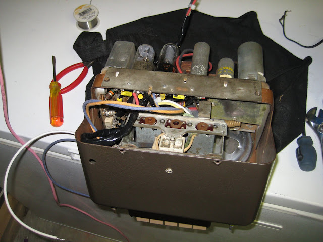
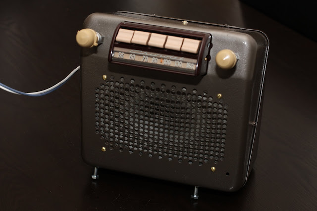
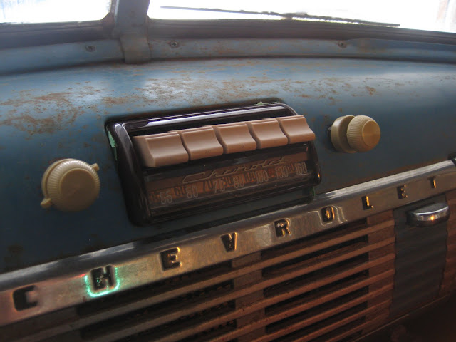
And I couldn’t possibly wait to have the truck rebuilt before giving the radio a test fit! And maybe even a test power on!

Hello,
Have you had any trouble using the 3.5mm audio jack in the tube radio? Thanks for all of the tips, I enjoyed reading through your restoration articles
Thanks Adam!
No, no problem at all. The sound is pretty clear and ultimately I will listen to the radio in this mode always – likely streaming a local radio station over my iPhone!
Mark